Gp2600 Proface Manual
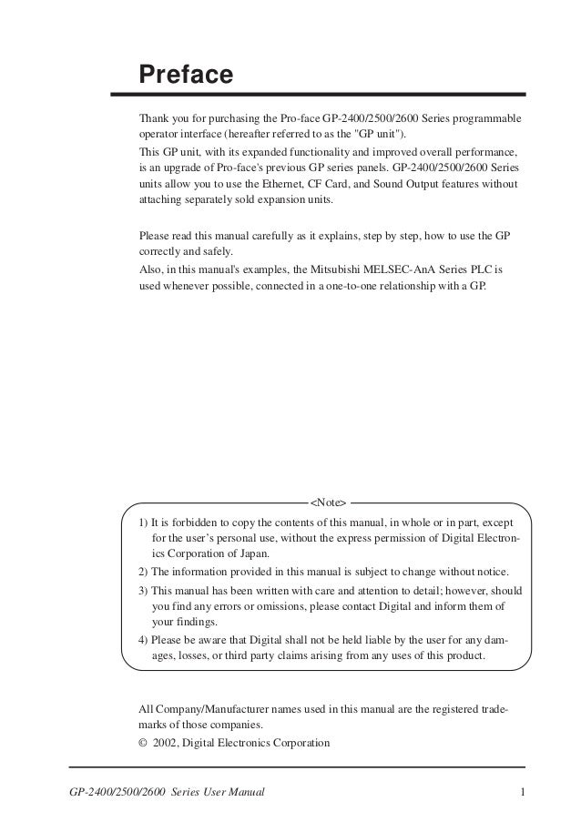
1 Thank you for purchasing the Pro-face GP-2400/2500/2600 Series programmable operator interface (hereafter referred to as the 'GP unit'). This GP unit, with its e xpanded functionality and improved overall performance, is an upgrade of Pro-face's previous GP series panels.


Proface Distributors
WARNINGS System Design • Do. • Storing this unit in areas at a temperature lower than is recommended in this manual’s specifica.
GP-2400/2500/2600 Series units allow you to use the Ethernet, CF Card, and Sound Output features without attaching separately sold expansion units. Please read this manual carefully as it explains, step by step, how to use the GP correctly and safely. Also, in this manual's examples, the Mitsubishi MELSEC-AnA Series PLC is used whenever possible, connected in a one-to-one relationship with a GP. 1) It is forbidden to copy the contents of this manual, in whole or in part, except for the user’s personal use, without the express permission of Digital Electron- ics Corporation of Japan.
2) The information provided in this manual is subject to change without notice. 3) This manual has been written with care and attention to detail; however, should you find any errors or omissions, please contact Digital and inform them of your findings.
4) Please be aware that Digital shall not be held liable by the user for any dam- ages, losses, or third party claims arising from any uses of this product. All Company/Manufacturer names used in this manual are the registered trade- marks of those companies. © 2002, Digital Electronics Corporation.
. Essential Safety Precautions WARNINGS System Design. Do not create GP touch panel switches that could possibly endanger the safety of equipment and personnel. Damage to the GP, its I/O unit(s), cable(s), and other related equipment can cause an output signal to remain continuously ON or OFF and possibly cause a major acci- dent. CAUTIONS Installation. Be sure to securely connect all cable connectors to the GP. A loose connection may cause incorrect input or output.
Wiring. Ground the GP's FG line separately from other units’ FG lines. Putting these FG lines too close may cause an electric shock or unit malfunction. UL/c-UL(CSA) Approval The GP2500-TC41-24V and the GP2600-TC41-24V are UL/c-UL(CSA) listed products. E182139) This Unit conforms as a component to the following standards: UL508 Industrial Control Equipment UL1604 Electrical Equipment for Use in Class I and II Division 2 and Class III Hazard- ous (Classified) Locations CAN/CSA-C22.2, No.1010-1.
Package Contents The following items are included in the GP's package. Before using the GP, please confirm that all items listed here are present.
GP Unit (1) Installation Guide (1) (GP2500-TC41-24V/ GP2600-TC41-24V) Installation Guide Installation Fasteners (4) Installation Gasket (1) This unit has been carefully packed, with special attention to quality. (Half Pitch 20-pin) N: Ethernet Interface O: Screw Lock Terminal Block P: Tool Connector Connects a Data Transfer Cable or bar code reader Dimensions 30111.85 Unit:mm in 582.28 80.31 (GP2500-TC41-24V/GP2600-TC41-24V) 31712.48 31712.48 Side (GP2500-TC41-24V/ GP2600-TC41-24V) Front Front (GP2500-TC41-24V) (GP2600-TC41-24V). Dip Switches These switches are located inside the CF Card's cover. Dip Switches Rear View of GP Dip Switch Function Note This Dip switch Startup from Startup from CF Card with setting controls CF Card is CF Card is startup data the startup from a enabled. Interfaces Serial Interface (HOST-I/F) This interface is used to connect the GP to the host (PLC), via an RS-232C or RS- 422 cable.
Signal Pin Arrangement Pin # Meaning Name Frame Ground Send Data (RS-232C) Receive Data (RS-232C) Request to Send (RS-232C) Clear to Send (RS-232C) Data Set Ready (RS-232C) Signal Ground. Use rough metric type M2.6 x 0.45p threads to hold the cable’s set (fastening) screws in place. When creating a cable, please be aware of the following:.
The following pairs of pin no.s must be connected (shorted).#18 (CSB). Screw Lock Terminal Block (12 pin) This interface performs external reset, remote I/O and sound output. Pin Arrangement Pin No. Signal Name Meaning External Reset AUXCOM External Reset Common AUXRESET External Reset Input Online ALARM System Alarm Output OUTCP 24VDC BUZZ External Buzzer Output Reserved. GP's power supply is completely turned OFF, via a breaker, or similar unit.
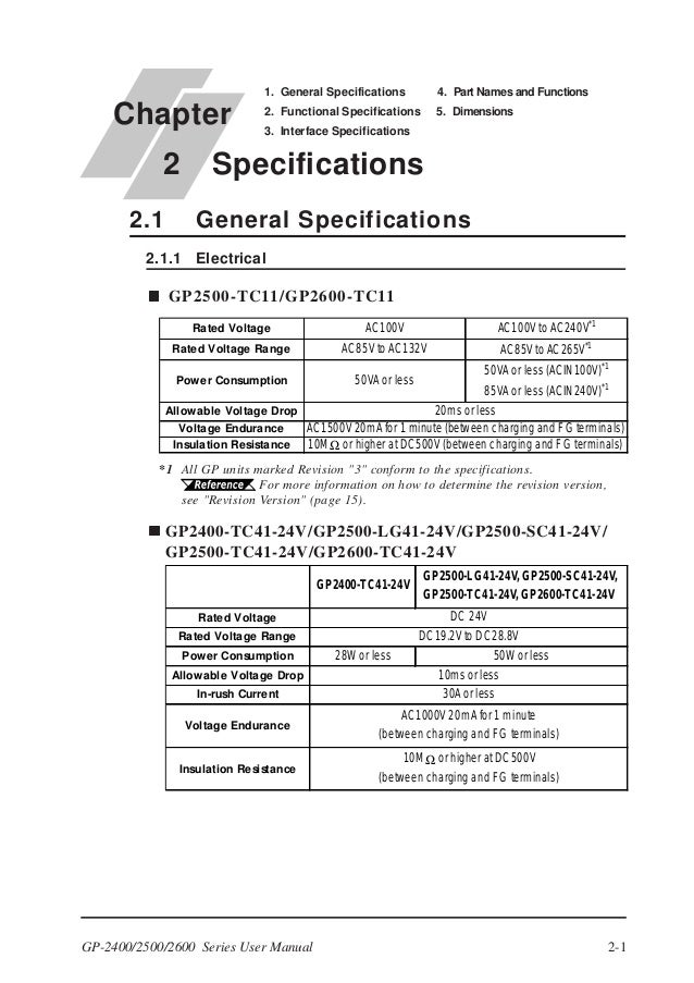
The GP2500-TC41-24V/GP2600-TC41-24V units are designed to use only DC24V input. Any other power level can damage both the GP and the power supply. To avoid a short caused by loose ring terminals, be sure to use ring terminals with an insulating sleeve. When the FG terminal is connected, be sure the wire is grounded.
Not grounding the GP unit will result in excess noise and vibra- tion.1 Use a grounding resistance of 100 Ω, a wire of 2mm or thicker, or your country's applicable standard.2 For GP-2600 Series, the backlight differs depending on a Rev. For the correct backlight and how to distinguish Rev., refer to the User Manual carried in the Pro-face Web Site (http://www.pro-face.com/).